

■ System Configuration
■ Product Introduction
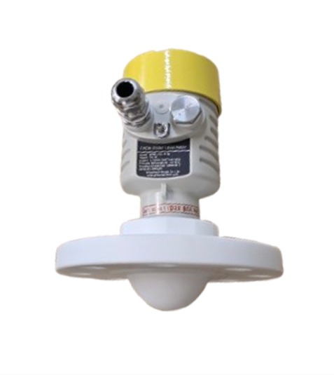
GFMR-80 부식방지형 시리즈는 FMCW 80GHz 고주파수 비접촉식 레이더 레벨/거리 미터는 76~81GHz 대역의 초고주파 FMCW(주파수 변조 연속파) 방식을 채택한 최첨단 비접촉식 계측 솔루션입니다. 기존 모델 대비 안테나 개구면(넓이)을 대폭 확장 설계하여 신호의 송수신 효율과 집중도를 극대화했습니다. 빔 각도가 한층 더 정밀해진 덕분에 탱크 내부의 복잡한 구조물이나 벽면 간섭을 완벽에 가깝게 회피하며 수면 및 타겟을 정확히 조준하고 확장된 안테나와 진보된 알고리즘의 결합으로 ±1mm 오차 범위 내의 초정밀(High-Precision) 계측을 실현하였으며, 수면의 미세한 출렁임이나 가혹한 현장 노이즈 속에서도 흔들림 없이 일관되고 정확한 수위 및 거리 데이터를 제공하는 고성능 하이엔드 표준형 레이더 수위계입니다.
In particular, the GFMR-80 (PTFE Type) is a specially structured product in which the entire antenna assembly is fully sealed and shielded with PTFE (fluororesin) for measuring highly corrosive chemicals and high-purity fluids. It fundamentally protects the sensor from gases or liquids that cause metal corrosion, and its excellent anti-adhesive surface properties allow it to stably transmit and receive high-precision 80GHz radar signals even in environments with highly viscous fluids or rising vapors.
■ Applications
Strong Acid & Strong Alkali Storage Tanks: Chemical tanks and chemical dosing processes requiring exceptional corrosion resistance against hydrochloric acid, sulfuric acid, nitric acid, caustic soda, etc.
Chemical Reactors & Plating Processes: Sealed reactors where high-temperature corrosive gases and harsh chemical vapors are continuously emitted upward.
Food, Beverage & Pharmaceutical Processing: Storage tanks that require highly clean (Sanitary) sealed management and essential hygienic cleaning.
High-Viscosity & Crystallizing Fluids: Wastewater and chemical sludge tanks where foreign substances easily adhere, condense, or crystallize on the antenna surface, which typically causes malfunctions in standard meters.
■ Key Features
- Based on a newly developed CMOS millimeter-wave RF chip, it realizes a more sophisticated RF architecture and increases the signal-to-noise ratio to ensure a minimal dead band (Dead band: 80mm or less / based on liquids).
- A 5GHz operating frequency bandwidth delivers higher measurement resolution and accuracy.
- The antenna beam angle is 3°, minimizing interference from the surrounding environment, dust, and water vapor.
- It offers excellent accuracy, with a margin of error of only 2–3mm.
- The short wavelength is designed to enhance frequency reflection characteristics on inclined target surfaces.
- It features a short response time 80~100ms and an adjustable measurement cycle 0.5~500m/Min.
- False echo frequencies can be easily eliminated.
- Support for remote debugging and remote upgrades helps reduce on-site labor costs.
Strong Acid & Strong Alkali Storage Tanks: Chemical tanks and chemical dosing processes requiring exceptional corrosion resistance against photocopying acid, sulfuric acid, nitric acid, caustic soda, etc.
Chemical Reactors & Plating Processes: Sealed reactors where high-temperature corrosive gases and harsh chemical vapors are continuously emitted upward.
Food, Beverage & Pharmaceutical Processing: Storage tanks that require highly clean (Sanitary) sealed management and essential hygienic cleaning.
- Equipped with a Korean language interface, allowing anyone to adjust it with ease.
■ Precautions
- Maintaining Wall Clearance Distance: To prevent distortion and interference, it must be installed at least 200mm away from the tank wall. A point at 1/4 or 1/6 of the tank diameter is most ideal.
- Avoiding Internal Obstacles & Inlets: Avoid obstacles inside the tank such as ladders, supports, and heating coils, as they can cause interference signals. In particular, never install directly above the inlet where raw materials fall.
- Compliance with Nozzle Extension Length: When installing on a tank top nozzle, it is recommended that the lens at the tip of the antenna protrudes into the tank at least 10mm past the bottom of the nozzle.
- Considering Maximum Water Level and Dead Band: A dead band zone exists directly in front of the sensor where signals cannot be detected. The installation height must be designed so that the maximum level of the tank does not enter this dead band.
- Rainwater Ingress Prevention: Tighten the waterproof cable gland securely and bend the cable downward into a "U" shape (drip loop) to prevent rainwater from running along the cable and entering the housing interior.
- PTFE Surface Scratch Prevention: During installation and transportation, use extreme caution to ensure that the surfaces of the Teflon lens and shield are not subjected to impacts or scratches caused by sharp metals or tools.
■ General Specifications
| Model | GFMR-80 | ||
|---|---|---|---|
| Frequency | 76~81GHz | ||
| Max. Measurement Distance | Standard Type | 10m, 20m | Liquid, Solid, Powder |
| Extended Range Type | 30m, 60m, 120m | Liquid, Solid, Powder | |
| Antenna Material & Size | PTFE, Ø70~80mm | ||
| Resolution | 1~2mm | ||
| Response Time | < 80~100ms | ||
| Measurement Cycle | Adjustable (1m/min ~ 300m/min) | ||
| Accuracy | < 2mm | ||
| Repeatability | < 1mm | ||
| Beam Angle | 3° | ||
| Dead Band | Liquid | 10m, 20m, 30m: 0.08~0.1m, 60m: 0.2~0.6m, 120m: 0.6m | |
| Solid, Powder | 10m, 20m, 30m: 0.1~0.5m, 60m: 0.2~0.6m, 120m: 0.6~0.8m | ||
| Min. DK Value for Measurement | 1.5~1.8 | ||
| Power Supply |
2-Wire, 4-Wire, 6-Wire: DC 24V / 22.5mA Option: AC85-240V, 50~60Hz |
||
| Signal Output | 10m | 2-Wire: 4-20mA with HART | |
| 20m, 30m, 60m, 120m |
2-Wire: 4-20mA with HART 4-Wire, 6-Wire: 4-20mA, RS485 |
||
| Error Output | 4mA, 22mA or 20.5mA (Configurable) | ||
| Adjustment | 4-Button | ||
| Display | LCD Display, 128x64 pixels / Level, Distance, (Space), 4-20mA Current, % | ||
| Language | Korean, English | ||
| Process (Powder) Temp. | Standard: -40~85°C, -40~120°C, -40~180°C / Others: -40~1,200°C | ||
| Process (Powder) Press. | -1 to 4.0MPa (For other high pressures, please contact us) | ||
| Ambient Temp. | Output: -40°C~55°C, Indicator: -30°C~55°C | ||
| Ambient Humidity | ≤ 95%RH | ||
| Housing Material | Standard: Aluminum die-casting / Option: Stainless steel | ||
| IP Rating | IP67 | ||
| Antenna Type & Material | Lens Type Antenna / PTFE | ||
| Process Connection | G3.5 Thread Type, Flange Type, Adjustable Angle Flange | ||
| Cable Entry | NPT 1/2"-FM, G (PF) 1/2"-FM, M20X1.5 | ||
| Recommended Cable Spec | AWG18 or 0.75m㎡ | ||
| Accessories (Optional) | Cooling fin structure flange, compound cooling fin structure flange with separate quartz, adapter, waveguide, UV protection shield, etc. | ||
■ Product Selection Code
80GHz · Non-contact · FMCW · Smart · Radar · Level/Distance · Meter
- - Level, Distance (Space), 4-20mA current, Percentage
- - Material properties, Material characteristics and Wastage line
- - 10m, 20m: 2-Wire system: 4~20mA with Hart
- - 20m: 6-Wire system: 4~20mA with RS485/Modbus
| Model | Code | Antenna | Specification |
|---|---|---|---|
| GFMR-78G | Range | 10 | Max. 10m |
| 20 | Max. 20m | ||
| Connection | Standard Antenna | ||
| -T | Thread: G1.5” Male | ||
| -50 | Flange: DN50 (2”) / Separated mounting | ||
| -80 | Flange: DN80 (3”) / Separated mounting | ||
| -100 | Flange: DN100 (4”) / Separated mounting | ||
| -125 | Flange: DN125 (5”) / Separated mounting | ||
| X | Special option antenna — Pls check above antennas and record antenna code No. | ||
| Option | N | None | |
| H | Cooling fin for high-temperature | ||
| HC | Cooling fin for high-temperature, filter | ||
| O | Others. | ||
| Required Specifications for Product Ordering |
1) Base Product Model 2) Measurement Range and Maximum Upper Level/Distance 3) Type of Fluid, Process Temperature, and Process Pressure 4) Meter Connection Method and Size 5) Connection Flange Type and Antenna Material (Standard: SUS304, Option: SUS316, PTFE, PVDF) 6) Antenna Body Material (SUS304, SUS316, PTFE) 7) Tank Shape and Size: W, D, H 8) Tank Nozzle (Connection Pipe) Size 9) Cable Entry Size (M20·X·1.5 or 1/2” NPT) 10) Additional Options and Precautions |
(The specifications in this document are subject to change without prior notice due to technical upgrades.)