

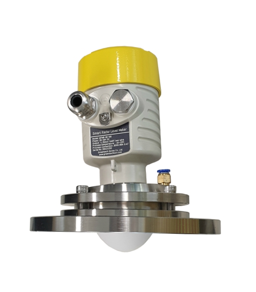
■ System Configuration
■ Product Introduction
The GFMR-80U Series, an FMCW 80GHz high-frequency non-contact radar level/distance meter, features a significantly expanded antenna aperture (width) compared to previous models, maximizing signal transmission/reception efficiency and focusing capability. Thanks to the even more precise beam angle, it perfectly circumvents wall interference and complex internal structures inside the tank, accurately targeting the water surface and target object.
The combination of the expanded antenna and advanced algorithms achieves ultra-high precision (High-Precision) measurement within an error margin of ±1mm. It is a high-performance, high-end standard radar water level gauge that consistently delivers stable and accurate level and distance data, even amidst fine surface ripples or severe on-site noise.
Furthermore, it is an innovative product that applies an adjustable universal flange system to maximize the accuracy and convenience of on-site installation. While flexibly compatible with standard off-the-shelf flange specifications (such as JIS), it allows users to freely adjust the fine angle of the antenna to suit the measurement medium and tank environment. This ensures the radar beam is perfectly aligned perpendicular to the fluid surface, preventing signal distortion and guaranteeing ultimate precision.
■ Applications
상부 경사 및 각도 보정이 필요한 탱크: 현장 설치의 정확성과 편의성을 극대화.
Smart Disaster Management & Water Resource Environments: Rivers, dams, reservoirs, and flood forecasting systems where reliability is the top priority.
Small Tanks & High-Density Chemical Reactors: Processes with limited internal space or numerous interference elements that require precise targeting.
Challenging Dust & Chemical Tanks: Dusty environments with flying coal, carbon, limestone, or cement, and environments with constantly coexisting highly corrosive gases.
Ultra-Precision Control Processes: Tanks requiring a high accuracy of ±1mm, where minute level changes directly impact product quality and safety.
Harsh Process Environments: Tanks with complex and adverse conditions that cannot be measured with conventional level meters.
Industrial Automation Lines: HMD (Hot Metal Detection), CMD (Cool Metal Detection), and other high-precision, non-contact distance measurement processes.
■ Key Features
- Based on a newly developed CMOS millimeter-wave RF chip, it realizes a more sophisticated RF architecture and increases the signal-to-noise ratio to ensure a minimal dead band (Dead band: 80mm or less / based on liquids).
- A 5GHz operating frequency bandwidth delivers higher measurement resolution and accuracy.
- 각도 조절형 유니버셜 플랜지
- The antenna beam angle is 3°, minimizing interference from the surrounding environment, dust, and water vapor.
- It offers excellent accuracy, with a margin of error of only 2–3mm.
- The short wavelength is designed to enhance frequency reflection characteristics on inclined target surfaces.
- It features a short response time 80~100ms and an adjustable measurement cycle 0.5~500m/Min.
- False echo frequencies can be easily eliminated.
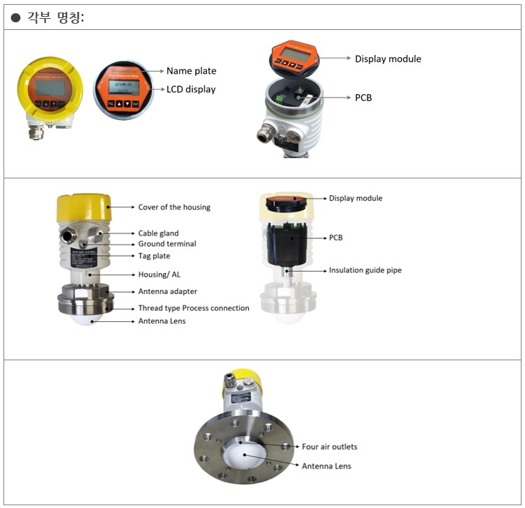
- The PTFE lens antenna is completely sealed to prevent frequency leakage, ensuring safe operation.
- Support for remote debugging and remote upgrades helps reduce on-site labor costs.
- Capable of measuring regardless of fluid type, including liquids, powders, and solids.
- Equipped with a Korean language interface, allowing anyone to adjust it with ease.
■ Precautions
- Maintaining Wall Clearance Distance: To prevent distortion and interference, it must be installed at least 200mm away from the tank wall. A point at 1/4 or 1/6 of the tank diameter is most ideal.
- Avoiding Internal Obstacles & Inlets: Avoid obstacles inside the tank such as ladders, supports, and heating coils, as they can cause interference signals. In particular, never install directly above the inlet where raw materials fall.
- Compliance with Nozzle Extension Length: When installing on a tank top nozzle, it is recommended that the lens at the tip of the antenna protrudes into the tank at least 10mm past the bottom of the nozzle.
- Considering Maximum Water Level and Dead Band: A dead band zone exists directly in front of the sensor where signals cannot be detected. The installation height must be designed so that the maximum level of the tank does not enter this dead band.
- Rainwater Ingress Prevention: Tighten the waterproof cable gland securely and bend the cable downward into a "U" shape (drip loop) to prevent rainwater from running along the cable and entering the housing interior.
■ General Specifications
| Model | GFMR-80 | ||
|---|---|---|---|
| Frequency | 76~81GHz | ||
| Max. Measurement Distance | Standard Type | 10m, 20m | Liquid, Solid, Powder |
| Extended Range Type | 30m, 60m, 120m | Liquid, Solid, Powder | |
| Antenna Material & Size | PTFE, Ø70~80mm | ||
| Resolution | 1~2mm | ||
| Response Time | < 80~100ms | ||
| Measurement Cycle | Adjustable (1m/min ~ 300m/min) | ||
| Accuracy | < 2mm | ||
| Repeatability | < 1mm | ||
| Beam Angle | 3° | ||
| Dead Band | Liquid | 10m, 20m, 30m: 0.08~0.1m, 60m: 0.2~0.6m, 120m: 0.6m | |
| Solid, Powder | 10m, 20m, 30m: 0.1~0.5m, 60m: 0.2~0.6m, 120m: 0.6~0.8m | ||
| Min. DK Value for Measurement | 1.5~1.8 | ||
| Power Supply |
2-Wire, 4-Wire, 6-Wire: DC 24V / 22.5mA Option: AC85-240V, 50~60Hz |
||
| Signal Output | 10m | 2-Wire: 4-20mA with HART | |
| 20m, 30m, 60m, 120m |
2-Wire: 4-20mA with HART 4-Wire, 6-Wire: 4-20mA, RS485 |
||
| Error Output | 4mA, 22mA or 20.5mA (Configurable) | ||
| Adjustment | 4-Button | ||
| Display | LCD Display, 128x64 pixels / Level, Distance, (Space), 4-20mA Current, % | ||
| Language | Korean, English | ||
| Process (Powder) Temp. | Standard: -40~85°C, -40~120°C, -40~180°C / Others: -40~1,200°C | ||
| Process (Powder) Press. | -1 to 4.0MPa (For other high pressures, please contact us) | ||
| Ambient Temp. | Output: -40°C~55°C, Indicator: -30°C~55°C | ||
| Ambient Humidity | ≤ 95%RH | ||
| Housing Material | Standard: Aluminum die-casting / Option: Stainless steel | ||
| IP Rating | IP67 | ||
| Antenna Type & Material | Lens Type Antenna / PTFE | ||
| Process Connection | G3.5 Thread Type, Flange Type, Adjustable Angle Flange | ||
| Cable Entry | NPT 1/2"-FM, G (PF) 1/2"-FM, M20X1.5 | ||
| Recommended Cable Spec | AWG18 or 0.75m㎡ | ||
| Accessories (Optional) | Cooling fin structure flange, compound cooling fin structure flange with separate quartz, adapter, waveguide, UV protection shield, etc. | ||
■ Product Selection Code
80GHz · Non-contact · FMCW · Smart · Radar · Level/Distance · Meter
- - Level, Distance (Space), 4-20mA current, Percentage
- - Material properties, Material characteristics and Wastage line
- - 10m, 20m: 2-Wire system: 4~20mA with Hart
- - 20m: 6-Wire system: 4~20mA with RS485/Modbus
| Model | Code | Antenna | Specification |
|---|---|---|---|
| GFMR-78G | Range | 10 | Max. 10m |
| 20 | Max. 20m | ||
| Connection | Standard Antenna | ||
| -T | Thread: G1.5” Male | ||
| -50 | Flange: DN50 (2”) / Separated mounting | ||
| -80 | Flange: DN80 (3”) / Separated mounting | ||
| -100 | Flange: DN100 (4”) / Separated mounting | ||
| -125 | Flange: DN125 (5”) / Separated mounting | ||
| X | Special option antenna — Pls check above antennas and record antenna code No. | ||
| Option | N | None | |
| H | Cooling fin for high-temperature | ||
| HC | Cooling fin for high-temperature, filter | ||
| O | Others. | ||
| Required Specifications for Product Ordering |
1) Base Product Model 2) Measurement Range and Maximum Upper Level/Distance 3) Type of Fluid, Process Temperature, and Process Pressure 4) Meter Connection Method and Size 5) Connection Flange Type and Antenna Material (Standard: SUS304, Option: SUS316, PTFE, PVDF) 6) Antenna Body Material (SUS304, SUS316, PTFE) 7) Tank Shape and Size: W, D, H 8) Tank Nozzle (Connection Pipe) Size 9) Cable Entry Size (M20·X·1.5 or 1/2” NPT) 10) Additional Options and Precautions |
(The specifications in this document are subject to change without prior notice due to technical upgrades.)